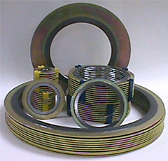
SpiroNat
We manufactur “SpiroNat” spiral-wound gaskets and are committed to providing our customers requirements in the most expeditious manner possible.
How to Order
-
NPS
Nominal Pipe Size
-
PSI
ANSI Pressure
-
Style
-
Material
Winding and Filler Material
-
Series or Thickness
Examples
-
Standard API 601 NPS 3� PSI 150# Style XR Material 304ss/Natfite Series/Thickness – -
Large Diameter NPS 36� PSI 150# Style XR Material 304ss/Natfite Series Series A -
Winding Only (SX) NPS 2 1/8� x 3 1/8� PSI – Style SX Material 304ss/Natfite Thickness 1/8� thick
Thickness available on custom made gaskets 1/8″, 3/16″, and 1/4�
-
Spiralwoud Style Code SX Winding Only SXI Winding with Inner Ring XR Winding with Guide Ring XRI Winding with Guide and Inner Ring XR-LP Low Pressure Winding with Guide Ring HL Winding with Loop Centering Guide XH * Winding Only XMCR Winding with Special (steel wound) Inner Ring * Manhole or Handhole gasket (specify shape)
-
Non-metallic filler winding material Natfite (Non-Asbestos) Teflon NS Teflon Glass Filled Teflon Ceramic GTB Grafoil GTA Grafoil -
Stainless Steel Metal Winding Materials 340ss 304L 316L 321ss 347ss 410ss Alloy 20 Hastelloy B Hastelloy C Inconel 600 Inconel 625 Inconel 750 Monel 400 Nickel 200 Titanium
Gasket Dimensions
Style and Color Code
-
Stainless Steel Color Code 304ss Yellow 304L Yellow 316L Green 321ss Turquoise 347ss Blue 410ss No Color Alloy 20 Black Hastelloy B Brown Hastelloy C Beige Inconel 600 Gold Incoloy 800 White Monel 400 Orange Nickel 200 Red Titanium Purple
-
Filler Material Color Code Natfite (Aramid Fiber) Pink Teflon White N.S. Teflon White Glass Filled Teflon No Color Ceramic Light Green GTB Grafoil Gray -
Spiralwound Style Code SX Winding Only SXI Winding with Inner Ring XR Winding with Guide Ring XRI Winding with Guide and Inner Ring XR-LP Low Pressure Winding with Guide Ring HL Winding with Loop Centering Guide XH * Winding Only XMCR Winding with special(steel wound) Inner Ring
* Manhole or Hanhole gasket (specify shape)
Style XR and XRI Spiralwound gaskets are manufactured in accordance with all relevant gasket standards per flange designations of ASME/ANSI B16.5, B16.20, B16.47, (series A and B API 605 and MSS-SP44)
Temperature Limits
All technical advise and recommendation are rendered by Seller free of charge. While based on data believed to be reliable, seller assumes no responsibility.
Weight
NPS Nominal Pipe Size
-
150# NPS 150# 1/2� 1 oz 3/4� 1-1/2 oz 1� 2 oz 1 1/4� 2 oz 1 1/2� 2-1/2 oz 2� 3-1/2 oz 2 1/2� 5-1/2 oz 3� 6 oz 4� 8-1/2 oz 5� 9-1/4 oz 6� 10 oz 8� 1 lb 10� 1-1/4 lb 12� 1-1/2 lb 14� 2-1/4 lb 16� 2-1/2 lb 18� 2-3/4 lb 20� 3-1/2 lb 22� 3-3/4 lb 24� 3-3/4 lb 30� 6-1/2 lb 36� 8-1/2 lb 42� 10-1/2 lb 48� 12-1/2 lb -
300# NPS 300# 1/2� 1-1/2 oz 3/4� 2-1/2 oz 1� 2-1/2 oz 1 1/4� 3 oz 1 1/2� 4 oz 2� 4-1/2 oz 2 1/2� 6-1/2 oz 3� 7 oz 4� 9-1/2 oz 5� 12 oz 6� 1 lb 8� 1-1/2 lb 10� 1-3/4 lb 12� 2-1/4 lb 14� 3-1/2 lb 16� 4-1/4 lb 18� 5 lb 20� 6 lb 22� 6-3/4 lb 24� 7-1/2 lb 30� 10-1/2 lb 36� 12-1/2 lb 42� 14-1/2 lb 48� 16-1/2 lb -
600# NPS 600# 1/2� 1-1/2 oz 3/4� 2-1/2 oz 1� 2-1/2 oz 1 1/4� 3 oz 1 1/2� 4 oz 2� 4-1/2 oz 2 1/2� 6-1/2 oz 3� 7 oz 4� 14 oz 5� 1 lb 6� 1-1/2 lb 8� 2 lb 10� 3-1/8 lb 12� 4-1/4 lb 14� 4-1/2 lb 16� 5 lb 18� 6 lb 20� 7-1/2 lb 22� 8-1/4 lb 24� 9 lb 30� 12 lb 36� 15-1/2 lb 42� 17 lb 48� 19 lb
Tolerance Tables
-
Standard Inner Ring Tolerance Size I.D. O.D. + – + – 1″ to 3″ + .0312 – .000 + .0312 – .0312 4″ or larger + .0625 – .000 + .0625 – .0625 -
Special Inner Ring Tolerance Size I.D. O.D. + – + – 1″ to 3″ + .0156 – .000 + .0312 – .000 4″ or larger + .0312 – .000 + .0625 – .000 -
XR Gaskets Tolerance Table
(Gasket with container outer ring)Size I.D. O.D. + – + – 1/2″ to 8″ + .0156 – .000 + .0312 – .0312 10″ to 24″ + .0312 – .000 + .0312 – .0312 26″ to 60″ + .0312 – .000 + .0625 – .0625 -
Guide Rings Tolerance
Size I.D. O.D. + – + – 1/2″ to 8″ + .0312 – .312 + .000 – .0312 10″ to 24″ + .0625 – .0312 + .000 – .0312 26″ to 60″ + .0625 – .0625 + .000 – .0312 -
Table of Standard Tolerance
For Special GasketsSize I.D. O.D. + – + – Up to 1″ + .0156 – .000 + .000 – .0312 1″ to 24″ + .0312 – .000 + .000 – .0312 24″ to 36″ + .0468 – .000 + .000 – .0625 36″ to 60″ + .0625 – .000 + .000 – .0625 -
Compression Table
Gasket Thickness Maximum Flange Width Optimum Compression Thickness 0.125 3/4″ .090-.100 0.175 3/4″ .125-.135 0.25 3/4″ .180-.200 0.285 3/4″ .200-.220
Note: 125-250 AARH is the optimum flange finish (Concentric or phonographic)